Ultrasonic Testing in Mining
Testing the Thickness of Reinforced Rubber Conveyor Belts
Conveyor belts are widely used across many industrial sectors, especially in mining industries. Abrasion of the carrying and pulley covers is one of many signs indicating this kind of wear and tear.
Decrements in a belt's cross-section reduce its puncture resistance, thus increasing the risk of damage to its core. If the rubber belt in conveyor systems fails, this can lead to unexpected downtime in a plant and also poses major safety risks.
Find out more about A-/B-Scan Thickness Gauge SONOWALL 70

Measurement Method
The primary purpose of thickness measurements is to determine the trended wear pattern and rate of wear for reinforced rubber belts. This maximizes the life of the rubber belt by predicting the end of its lifespan. As such, thickness measurement is a tool for effective maintenance and also allows belt changes to be incorporated into the relevant budget cycle.
Why ultrasonic testing is needed
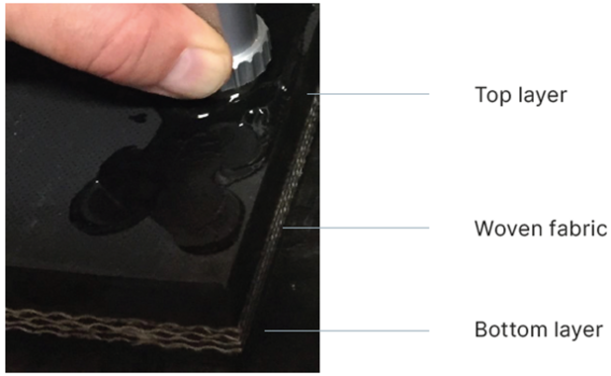
Reinforced rubber conveyor belts are made of many layers of rubber as well as woven fabric or steel cords, or combinations of these. This means that the production process is rather complicated and many joints are required. These joints are formed by vulcanization. During this process, there is a chance that delamination (air pockets) may form in the joints of the conveyor belt. This defect is caused mainly by incorrect vulcanizing pressure or curing temperatures during the joining process. If the joints contain delamination, they will fail when used in harsh conditions. Therefore, conveyor belt manufacturers also need to carry out ultrasonic tests to check the depth and the location of the reinforcement layer throughout the belt to ensure that the product meets the required specifications.
Challenges
Lack of proper calibration points over the belt cross section
Some conveyor belts are made using different types of rubber in different layers. This means that a calibration through the total thickness is actually a measurement of the average velocity at the current thickness and in the current location. Conveyor belts wear in the center but most calibrations are performed on the edge, where the steel cords or fabric layers are normally not present. The fabric layer is a series of peaks and troughs, so the true thickness is really an estimate depending where the probe is situated. The SONOWALL 70 meets this challenge and offers different calibration options that are all easy to execute. SONOTEC recommends taking a measurement at the side of the belt where the operator can make a one-point calibration over the total thickness.
External conditions: Temperature & aging
The ambient temperature and aging caused, for example, by damage from the sun affect the sound velocity in rubber. This is a much bigger issue in rubber than in steel. If the temperature of rubber increases by 10°C to 20°C, this changes the thickness reading by at least a couple of millimeters. Some operators monitor the temperature of the rubber when they take the reading. In theory, they could then make adjustments to the readings or try to repeat the test the next time at roughly the same time of day. Other operators revert to night-time testing as the temperature of the rubber during the daytime exceeds their probes' limits.
The most effective way to eliminate the temperature effect is to carry out regular calibrations on the hot rubber. A reading in the morning will be very different to an afternoon reading. And measuring rubber below 10°C is too difficult because it gets stiff. So the operator may have to wait for the rubber to warm up before starting the day's readings. Thanks to the higher pulser voltage (400 V) of the SONOWALL 70 thickness gauge, operators can start comparatively earlier in the day.
The challenge of measuring cord thickness
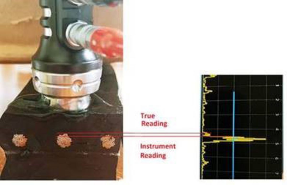
There are two issues related to cord readings and both are caused by the way in which cords are made. Cords are bundles of spiraling wires. As such, the thickness measurement varies depending on where the reading is taken along the wire. The other issue is that the apparent thickness reading shown on the instrument is different to the actual physical thickness of the cord. The instrument reading plots out just below the surface of the cord. There are a number of factors at play here. Usually, a 2 MHz twin crystal probe is used.
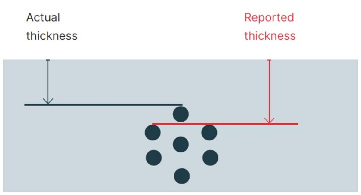
The wavelength is probably too big to read the very first wire in the cord. Also, it may be too difficult to isolate the target wire on the display (the high resolution and crisp picture provided by the SONOWALL 70 is an advantage here) so the main echo is used instead as the true thickness. Some companies apply a correction factor but the majority do not. Out in the field, operators do not have the time to find these small signals so they record the main echo.
Measurement repeatability (location)
The datum points used to repeat thickness readings over time are not fixed. Some operators try to find the same test location on the next survey. Others do not. There is no perfect solution here, so assumptions are made about how uniform the readings are over the whole conveyor belt. Only a fraction of the belt is tested at any given shutdown.
Measuring the total belt thickness
As the challenges presented above show, reinforced rubber is a rather difficult material to test using ultrasound as the attenuation inside its structure is quite high. It contains multiple layers of rubber and often even inserts of woven fabric, which prevent ultrasonic waves from penetrating the material easily. A large part of the sound energy reflects off the first layer of reinforcement. Some of it penetrates deeper into the material to reveal valuable information about the subsequent layers, especially if the belt contains fabric and steel cords.
Given the layered structure of the rubber, complete laminations can sometimes be seen in the rubber. Some of the back wall echo can normally still be seen, however, the main issue here stems from untrained operators not recognizing the presence of laminations. This is the main reason why a high-resolution A-scan is essential as it provides the operator with a clear understanding of the internal condition of the test object. The SONOWALL 70 provides a high-resolution A-scan.
In some types of rubber, the attenuation is so severe that a much higher pulse voltage is required to read the top cover or to reach the back wall for calibration purposes. The low pulse voltage of many thickness gauges makes them unsuitable for these kinds of measurements. These kinds of conveyor belts usually have fire-resistant properties and are found in underground mines. We try to meet this challenge by integrating a stronger pulser (400 V) in our thickness gauge. However, ultrasonic testing of conveyor belts has its limits. It is not always possible to measure the total thickness of the belt. This especially applies to some steel-reinforced belts with fabrics where the steel cords are very close together. Prior to the inspection, a feasibility study should be carried out to determine the potential testing performance. This should include a wide selection of probes. SONOTEC and its distributors typically offer demonstrations on site to verify customers' requirements.
Measurement procedure
Given the above factors, it is not uncommon to find wide variations in thickness readings. These can be caused by variations between different operators and by one or more of the factors mentioned above. The most efficient way to proceed here is to eliminate as many errors as possible and make sure every operator tests in exactly the same way. Rubber is a very sound-attenuating material. In most cases, it is not possible to obtain two clear back wall echoes. As a result, the pulse echo technique is recommended here. This means that the equipment has to be set to single echo mode. SONOTEC recommends using dual-element probes. In this case, a V-path error correction curve must be set up for the probe used during the measurements.
Conveyor belt rubber is usually unique and may vary from belt to belt. The sound velocity should therefore be calibrated using a sample of known thickness(-es) of the exact rubber being inspected. Ideally, a two point calibration should be performed. This requires two reference thicknesses of the same material. If this is not possible, the suggested approach is to zero the probe and use a one-point calibration. The sound velocity of the kind of rubber typically used for conveyor belts should be around 1650 m/s. If a sample is not available, the recommended approach is to set up a V-path error correction, zero the probe and manually adjust the sound velocity. Measuring the rubber above the reinforcement fabric (top cover) is relatively easy. The fabric is oriented perpendicular to the ultrasonic beam propagation and has a significant acoustic impedance mismatch. In most cases, the amplitude signal will be much stronger and easier to evaluate than the back wall echo. Inspecting conveyor belts that consist of steel cords is more difficult. The cords are not positioned over the whole area. Locating them is difficult and has to be done by observing the amplitudes that appear before the expected back wall echo. The second difficulty stems from the round shape of the cord, which is not an ideal reflector.

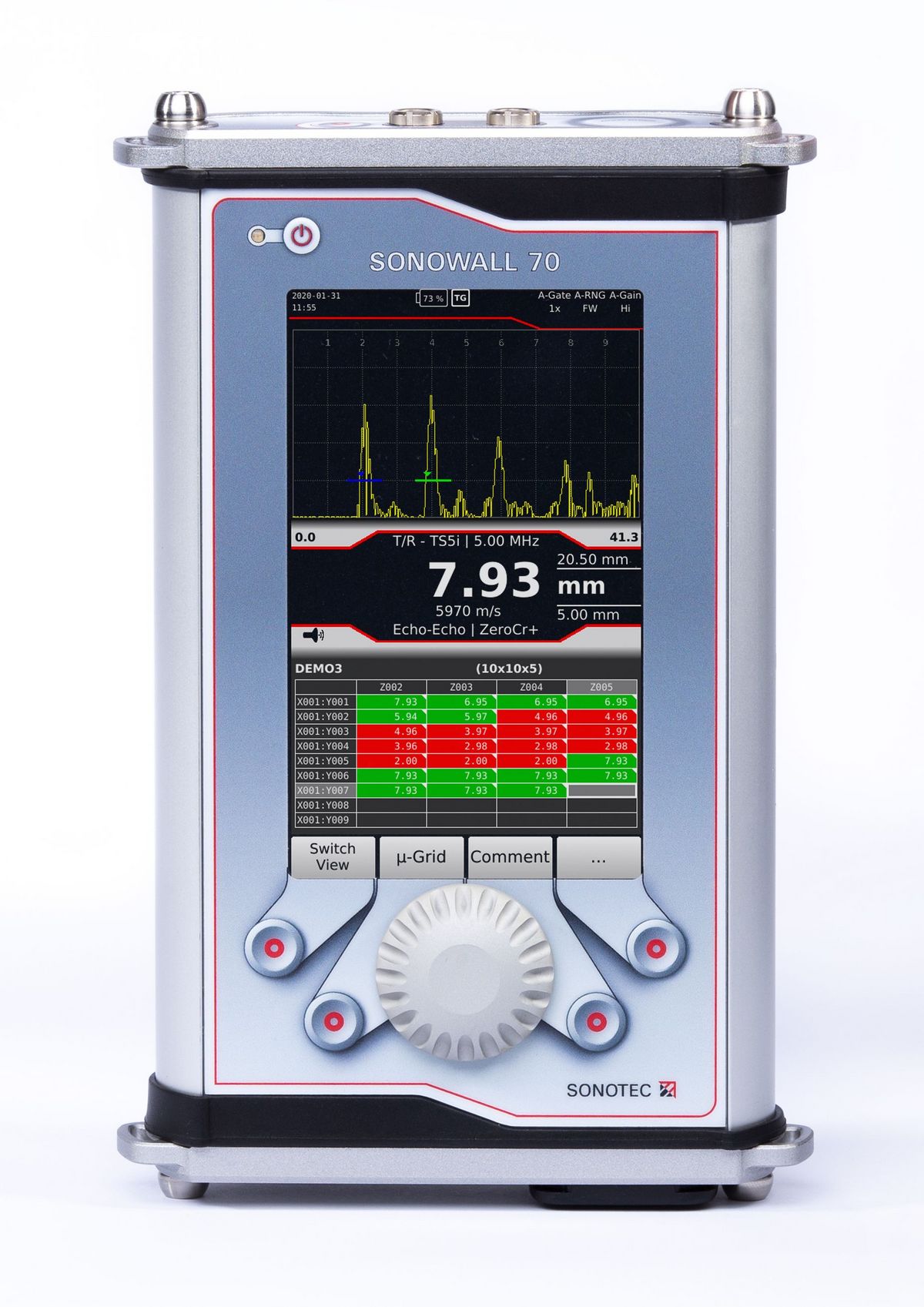
Recommended equipment: SONOWALL 70
The SONOWALL 70 advanced A-/B-scan thickness gauge has been successfully deployed for this kind of application. It shows great advantages over other thickness gauges and matches or exceeds the performance of flaw detectors available on the market. Using SONOWALL 70 for testing rubber belt conveyors brings many advantages for users:
Selecting probes
Belt thickness, composition and measuring accuracy will determine what probe you choose. In general, however, SONOTEC recommends:
- 0.5 mm to 5 mm dual-element 0 degree, piezo-composite, 5 MHz TS5i probe
- 3 mm – 50 mm dual-element, 0 degree, piezo-composite, 2 MHz TS2i probe
A major advantage of SONOWALL 70 is that it provides all-round software support for third-party probes, which gives it the capability to solve almost any potential task.
Features
- Improved thickness range due to signal strength (square wave 400 V transmitter) and the option of using low-frequency probes (down to 0.5 MHz, single or dual elements)
- Greater accuracy due to improved signal quality (averaging, digital filter selection, low-noise amplifier up to 110 dB dynamic range)
- Faster measurement times due to flexible software that allows automated functions to be adjusted (Auto Gates, Auto Gain and Auto Range)
- Fast reporting due to a comprehensive data logger that can be easily exported to Excel (*.xls), PDF or CSV files
Do you have any questions?
Feel free to contact us! We will be happy to help you.